Pluggable DB
Instead of implementing a proprietary DB solution for Dragonflow or picking one open source framework over the other, we designed the DB layer in Dragonflow to be pluggable.
The DB framework is the mechanism to sync network policy and topology between the CMS and the local controllers and hence control the performance, latency and scale of the environments Dragonflow is deployed in.
This allows the operator/admin the flexibility of choosing and changing between DB solutions to best fit his/her setup. It also allows, with very minimal integration, a way to leverage the well tested and mature feature set of these DB frameworks (clustering, HA, security, consistency, low latency and more..)
This also allows the operator/admin to pick the correct balance between performance and latency requirements of their setup and the resource overhead of the DB framework.
Adding support for another DB framework is an easy process, all you need is to implement the DB driver API class and add an installation script for the DB framework server and client.
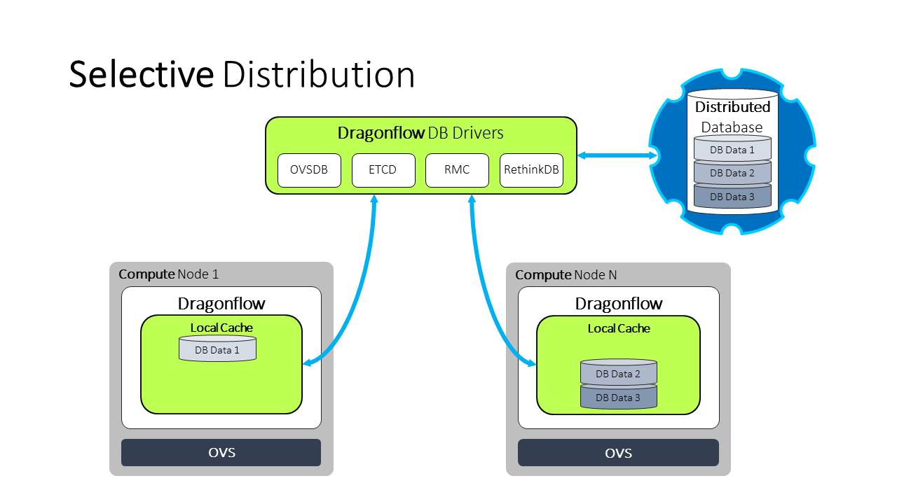
The following diagram depicts the pluggable DB architecture in Dragonflow and the currently supported DB frameworks:

Classes in the DB Layer
The following sections describe the two main classes that are part of the DB layer.
Applicative N/B DB Adapter Layer
This component is the translator layer between the data model elements to the DB driver which is generic.
This class should be used by all Dragonflow users that need to interact with the DB (write/read). For example: Dragonflow Neutron plugin, the Dragonflow local controller, external applications.
This component was added for one main reason: We didn’t want to expose the DB driver to the internal data schema/model of Dragonflow. We didn’t want that every new feature in Dragonflow will trigger changes in the various different DB drivers.
This component has an interface to add/set/delete elements in our model (like logical switches, logical routers and so on) and translate these APIs to a simple, generic key/value operations that are done by the DB driver.
This component also define the Dragonflow data model objects and which fields each one of the logical elements has.
The N/B DB Adapter has a reference to a DB Driver instance which is used to interact with the DB framework. We have identified that different DB frameworks might have different features and capabilities, this layer is in charge of understanding the features exposed by the driver and using them if possible.
DB Driver API
DB Driver is an interface class that list the methods needed to be implemented in order to connect a certain DB framework to work with Dragonflow as a backend.
The DB driver is a very minimalistic interface that uses a simple key/value approach and can fit to almost all DB frameworks.
In order for Dragonflow to be able to leverage “advance” features of the DB, the driver has a way to indicate if a specific feature is implemented or not, and if it is, provide an API to consume it.
Using this method, the applicative DB adapter can choose the best way to manage the way it interact with the DB.
For example: the driver can state if it support publish-subscribe on its tables, If it does, the local controller will register a callback method to the driver to receive any DB notifications and instead of polling the DB for changes, wait for the driver to send them.
If the driver doesn’t support publish-subscribe, the controller will keep polling the DB framework looking for changes.
Modes of DB
There are three different modes for the interaction between Dragonflow and the DB.
Full Proactive
In this mode, all the DB data (policy and topology) is synced with all the local Dragonflow controllers (each compute node). Dragonflow saves in a local in-memory cache all the data that was synced from the DB in order to do fast lookups.
Selective Proactive

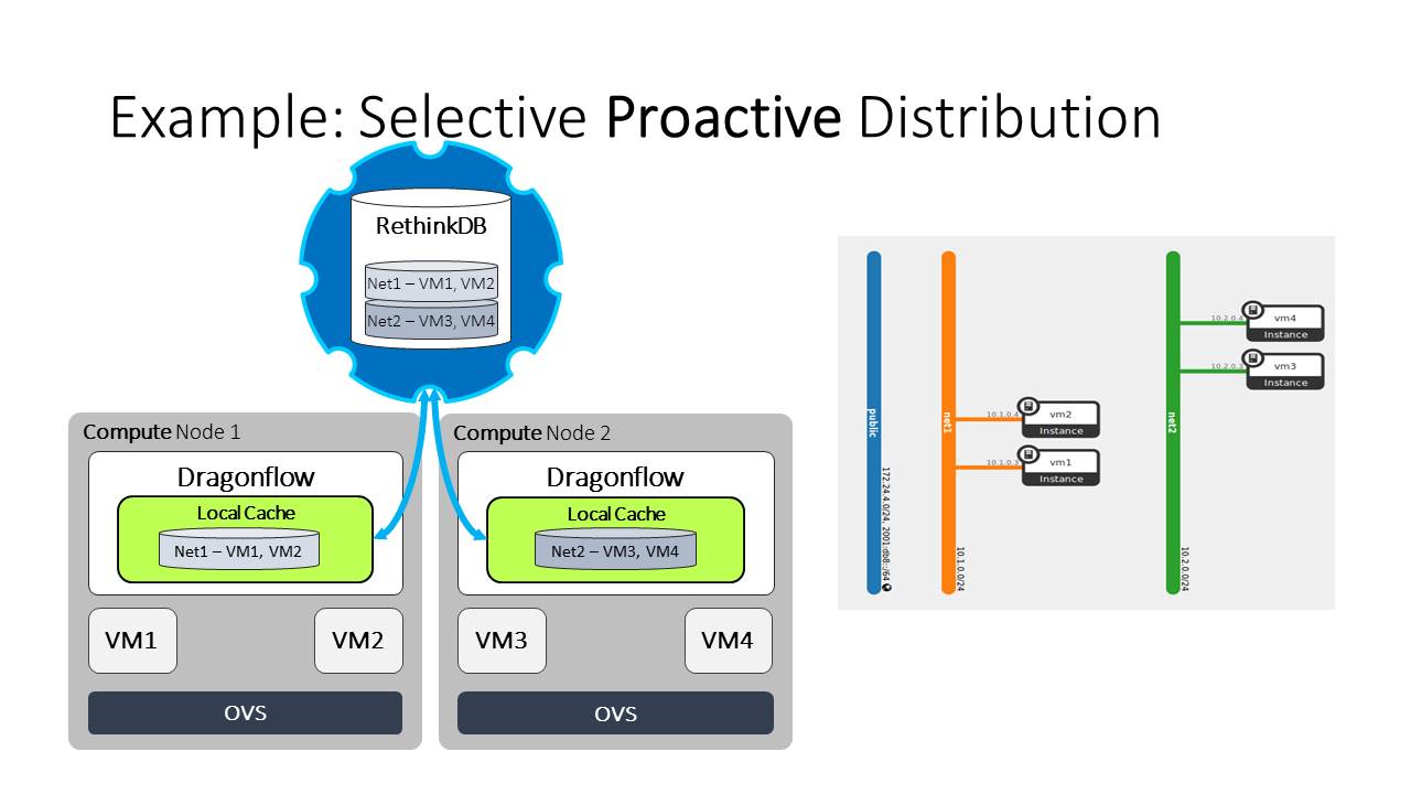
We have identified that in virtualized environments today with tenant isolation, full proactive mode is not really needed. We only need to synchronize each compute node (local-controller) with the relevant data depending on the local ports of this compute node. This mode is called selective proactive.
The following diagram depicts why this is needed:

We can see from the diagram that each compute node has VMs from one network, and in the topology we can see that the networks are isolated, meaning VMs from one network can not communicate with VMs from another.
It is obvious than that each compute node only needs to get the topology and policy of the network and VMs that are local. (If there was a router connecting between these two networks, this statement was no longer correct, but we kept it simple in order to demonstrate that in setups today there are many isolated topologies)
Reactive

Except where otherwise noted, this document is licensed under Creative Commons Attribution 3.0 License. See all OpenStack Legal Documents.